Checking and Truing a Planing Form
by Mike McGuire
I was dissatisfied with my hand-filed planing form. It was a lot of extra trouble to get good angles and dimensions especially with butt strips. I suspected it was the angle of the groove. I had made it by the usual method of setting a reverse taper. I filed with an adjustable depth file plane, so that a dial indicator with a 60 degree point would indicate a constant depth over the whole length of the form. The process is described in this article. It was an epic job, leaving me with an appreciation of what life must be like for those Khyber Pass gunsmiths who turn out whole AK47’s with just files and hand drills. Checking with a 60 degree fishtail/thread gauge didn’t show any problem. I needed something better.
There is a method for setting the depth of the form by laying a cylindrical rod of known diameter in the groove, and measuring the height it stands proud of the groove.
I came up with a variation of this using rods of two different diameters to measure the angle of the groove.
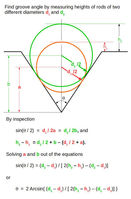
The value of the sine of the half angle is 0.5 if the angle is a true 60 degrees. Arcsin is mathspeak for the "angle whose sine value is ..."
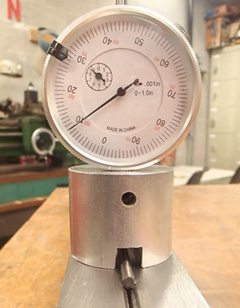
The most convenient way to measure is with a dial indicator with a flat point, in a fixture with a slot cut through it wider than the diameter of the largest rod used. It is zeroed against the top of the form.
For the rods I used drills from a good quality drill index. I mike'd them all around and found that they were round to within a ten thousandth or two, but were typically off a thousandth or so from their nominal diameters, so I used the measured diameters in the computations.
I set the planing form to a constant depth, D = 0.3125, at each station along its length. The filed depth of the form was 0.085 at the first station and 0.155 at the last 70 inches away.I decided to measure every 2.5 inches along the form. I wanted the contact points of the rods at each station to be widely spaced, the larger around 0.010 from the top of the groove and the smaller 0.010 above the bottom . Thus I could use one drill to measure all the stations at the top, but had to use an increasing progession of sizes for the lower measurement as the depth of the groove became shallower.
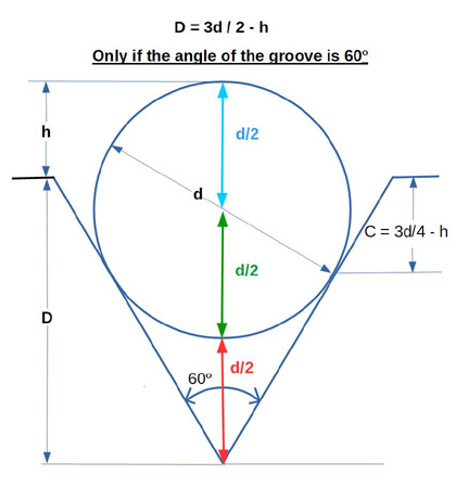
The contact depth C determined by the rod diameter d, and the height is
C = 3d/4 - h
With the set depth D we have
D = 3d/2 - h
From these two equations we can eliminate h to get the rod diameter d required for a given C
d = 4(D - C)/3
For the set depth D of 0.3125 and contact C around 0.010 the rod diameter d is 0.403. The closest drill in a 1/16 spaced set is 13/32 or 0.406 which is what I used. I calculated this table to determine rod diameters and the expected heights for the lower measurements of the groove.
| Contact Depth | Rod Dia | h |
| 0.010 | 0.404 | 0.293 |
| 0.020 | 0.391 | 0.273 |
| 0.030 | 0.377 | 0.253 |
| 0.040 | 0.364 | 0.233 |
| 0.050 | 0.351 | 0.213 |
| 0.060 | 0.337 | 0.193 |
| 0.070 | 0.324 | 0.173 |
| 0.080 | 0.311 | 0.153 |
| 0.090 | 0.297 | 0.133 |
| 0.100 | 0.284 | 0.113 |
| 0.110 | 0.271 | 0.093 |
| 0.120 | 0.257 | 0.073 |
| 0.130 | 0.244 | 0.053 |
| 0.140 | 0.231 | 0.033 |
| 0.150 | 0.217 | 0.013 |
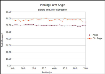
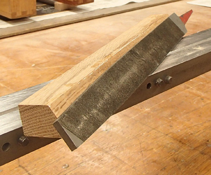
The results of the measurement were rather bad--an average of 68 degrees! I didn’t think taking the file plane to the groove was going to improve it, as it likely caused the problem in the first place. I took a half inch piece of hardwood about a foot long, to my table saw. I set the blade over to 30 degrees away from vertical. I checked this with a 30-60-90 drawing triangle rather than relying on the scale on the saw. I made a cut the length of the piece of wood, and glued a 12” long mill file to the sloping cut with epoxy.
I took the form apart and painted the side of the groove on each piece with a felt tip marker. I started in filing with the board sliding on the top surface of the form and the file working on the groove. With a few strokes I noticed that there were high and low spots revealed by removal and non-removal of the ink—not a surprising considering the results of the measurements. I continued filing until all the ink was removed. With the form reassembled, I measured again. The angles were much better, the average being 59.98. The filing didn’t much deepen the groove.