I have been the "victim" of a conspiracy in my fishing club to get me to teach some of the guys how to make bamboo fly rods. I'm flattered, but on thinking it through, I realized that while it would be no problem for them to use my heat treating oven or rough beveler, I didn't want my one an only planing form to be tied up for much time, so I decided to make a second one.
For the first one I made, I used the Waldron variation of the procedure described by Penrose. This I found good up to the point of cutting the 60 degree groove as described there. The idea is that a tapering gap is set between the bars such that when a triangular file has cut so that its apex is at the same distance from the surface all along the form a uniformly tapering groove has been cut. Thus the file has cut the least at the tip end, and the most at the butt end. A suitable slope for the taper is 0.001" per inch along the form. The method suggested is to use a dial caliper to set the spacings at each station such that each station is 0.006" further open than the last. A piece of triangular file glued to a wooden block would be used to cut the groove. The initial spacing would be set so that the file was almost flush at the widest point to minimize the side-to-side rocking of tool which could throw off the 60 degree angle. This would require readjustment of the tapered spacing as the groove gets deeper to maintain this almost flush condition. The achieved depth would be monitored by eyeballing a depth measurement with the caliper.
A better way to do this would be to set the spacings with rods of known diameter between the forms, to use an adjustable depth file holder, and to measure the achieved depth with a dial indicator with a 60 degree point. That way, one setting of the spacings would be all that was required. The file depth would be adjusted as needed to minimize rocking. The desired taper would be achieved when a uniform target depth as measured by the dial indicator is reached all up and down the form. These ideas are not necessarily all new, but I haven't seen them gathered together like this.
An ideal way to set the spacing between the forms would be a set of pin gages. These are precision ground steel pins in steps of 0.001" over a range of say 0.060" to 0.250". These would be used in steps of 0.006" to set the spacing at each of setting stations on the form. The push and pull bolts would be set so they just could barely be pulled out. The cheap alternative to the expensive gage set is a set of numbered drill bits, a micrometer, and some calculation. There is a diameter standard for each drill number, but on measuring them with a micrometer I found some variation. I also checked for roundness. The calculation is required, because the diameters are not uniformly spaced, so instead of being able to put them at the setting stations, their locations along the form have to be calculated. I set up an Excel spread sheet (downloadable at the bottom of this page). I did not use all the drills over the range of interest, but chose those spaced about 0.005--0.006" apart. The maximum diameter drill used must be less that the outside diameter of the dial indicator point so it doesn't slip between the forms. Here is an image of the spread sheet.
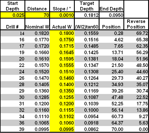
The yellow boxes are the inputs from the user. The Start Depth is the desired depth at the thin end of the groove. Shown here is a suitable value for the tip side. Something like 0.085 would be a good value for the butt side. The Distance is the length from the start to a desired end point. The Slope / " is the slope of the groove. Don't change it without a good reason. The actual measured values of the drill diameters are entered in the Actual W column. The Target Depth is the depth to file the groove to, the same all up and down the length of the form. It is to be measured with the dial indicator with 60 degree point. Position is the location of the drill along the length starting from the tip end. Reverse Position is measured from the opposite end.
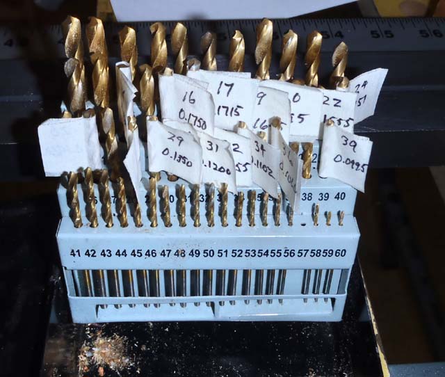
So I measured all my drills and tagged the ones I used with a bit of tape with the number and dimension as shown below.
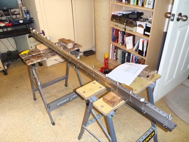
Here they are in place on the form. The from is adjusted so they can just barely be pulled out.
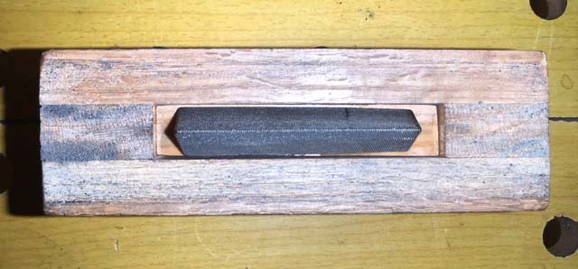
Here is the adjustable file plane.
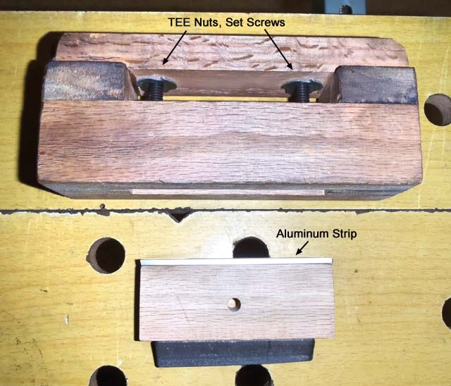
The adjustable part with the file fits in the slot in the bottom. The aluminum strip is because I found the wood was dimpling from the set screws. Structure of the plane is made from pieces of 1 1/2" x 3/4" milled red oak glued together. Some sort of lock nut on the set screws would have been good, but as constructed there wasn't space for it. However some D size rod wrapping thread through the TEE nuts provided enough friction. Below is a bottom view of the plane with with the file in place. Note the taper of the file piece--it made for smoother filing.
The zero of the dial indicator needs to be calibrated to get correct readings. This can not be reliably done by pressing the point against a flat surface because it is so easily damaged. Below is a picture of a calibration fixture I put into each side of the form.
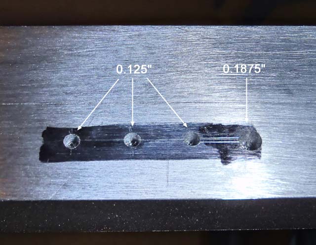
There are three holes, made first by drilling them with a 7/64" drill and then taking them to 1/8" (0.125") with an accurate reamer. When the point of the indicator is in one, it is set to read 0.1083". Why three holes? If one goes off, it is outvoted by the other two. The other hole is accurately reamed to 3/16" (0.1875") . This is a way to check if the point is a good 60 degree point. If the indicator is calibrated with a 1/8" hole, the indicator should read 0.1624" when inserted in to 3/16" hole.
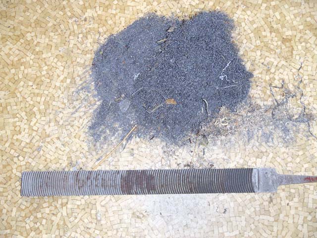
Below is a picture of a Vixen file, the preferred kind for flat filing the forms, along with the impressive pile of shavings the result from doing it.
Some notes on filing the groove--try to do the tip side of the form first, with the knowledge that it you overcut, you can always make it the deeper butt side. If the minimum tip dimension is as small as 0.025", it doesn't take very many file strokes to achieve it at that end--in general measure a lot as you approach the target dimension. Measure at each setting station and write the measurement on one bar of the form with a felt pen. The next time you measure write the result on the other bar. This tracks progress and gives you and idea of how you are doing. An alcohol wipe will take the writing off the form.
All told including the flat filing, you are in for 3 or 4 days of work to make the form. Likely it with give you some appreciation for what life is like for those Khyber Pass gunsmiths who produce whole AK47's with just files and hand drills.
Download the spread sheet. If you don't have Excel, there is a free alternative Open Office which you can download and install, which will run it.