A Bamboo Toaster
by
I have a requirement to be able heat treat strips of bamboo for a building fly rods to about 350° F. I used to bake out high vacuum systems at considerably higher temperatures using heating tapes wrapped around them. It occurred to me that a similar approach might work well for this requirement. Part of the requirement is that the temperature should be reasonably close to the same over the whole length of the bamboo strips.
The Oven Tube
I decided to use a 6 foot piece of copper tubing because as a good conductor of heat, it should help to keep the temperature even. A 1 inch nominal diameter tubing should be quite large enough to hold a bound up bundle of rough planed triangular strips in a hex configuration for any size rod I might want to build. It also would not require too much heating tape or a huge amount of power to reach the desired temperature. I got some slip-on end caps. I did a bit of sanding of the ends of the tube so they would fit easily.Heating Tape
I found a variety of tapes available from McMaster Carr at this link http://www.mcmaster.com/#3641k26/=od0k3. The one that seemed best was a 96 inch length of "Super High Temperature Heat Rope." for $45. It's good to 900° F which is well beyond my requirements, and at 400 watts in can be controlled with a rotary light dimmer which commonly can handle up to 600 watts.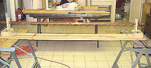
Heating Cord Wrapped on the Tube
In the picture above the tube is supported at each end by a piece of wood with a 1.25" hole through it. Below is a little box to which the wood is clamped. For actual use, the tube is supported by fire bricks. I got them at the ceramics/pottery supply house. They are very soft and easily cut, drilled etc. The little boxes are sized to fit them and are screwed to the board. See detail below. I used a stainless steel hose clamp at each end of the pipe to hold the heating cord in place
Temperature Measurement with Thermocouples
A thermocouple is the junction of two dissimilar metals which produces a voltage across them which varies with temperature. There are several standard ones. You can read all about them at this link http://en.wikipedia.org/wiki/Thermocouple. I chose use type K which is Chromel-Alumel, alloys of nickel etc. One can buy them made up and packaged, but they are extremely simple to make from thermocouple wire which is a pair of the two metal wires insulated from each other. Stripping the wires and twisting a few millimeters of them together at the end makes a junction. However at elevated temperature the wires oxidize, and the junction gets flakey. Ideally they should be welded together, but this takes a fairly high temperature torch or a small spot welder. What I do is cold weld them by hitting the twisted wires with a hammer on an anvil surface. Type K (and other types) is available from McMaster at this link http://www.mcmaster.com/#type-k-thermocouple-wire/=qzvbgl. I acquired 10' of the #24 900° fiberglass insulated wire at about $1 a foot. The wire color code for type K is yellow for positive, red for negative. The simplest way to read the thermocouple is to acquire a digital multimeter with a temperature probe capability. This will invariably be for the type K thermocouple. It will come with a thermocouple, but it will be pretty stingy on length. Prices run $30 and up. Note that in previous versions of this article on my web site, I used type T thermocouples (Copper-Constantan), but mad the switch for compatibility with the multimeter.Alternatively one can setup an ice water reference junction, read the voltage with a meter with range down into the millivolts and use the table below to convert to temperature. Otherwise skip the rest of this section down to Equalizing the Temperature
Thermocouples are used in pairs wired in opposition to each other. One of the junctions is held at a reference temperature, typically 0° C, the melting point of ice while the other is used to make the measurement. Multimeters with temperature probes create the reference electronically.
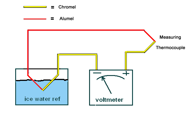
Thermocouple Hookup
Above is how a thermocouple measuring system is hooked up. It is really that simple. The colors correspond to the standard insulation colors for type K thermocouple wire. Now how to turn the voltage reading into degrees? Below is a table from the National Institute for Standards and Technology http://srdata.nist.gov/its90/main/, following the links to http://srdata.nist.gov/its90/download/type_k.tab. The excerpt below covers the range of interest. The design goal 350° F is 176°C. If °C is not comfortable, here is an online converter http://www.wbuf.noaa.gov/tempfc.htm
Now the millivolt range seen above may seem a problem, but it turns out that quite cheap digital multimeters available today have a 200 mV range with 0.1 mV resolution which is adequate for this job. I got the one in the picture below from Harbor Freight for $4.
 ITS-90 Table for type K thermocouple
 °C      0      1      2      3      4      5      6      7      8      9     10
                               Thermoelectric Voltage in mV

   0  0.000  0.039  0.079  0.119  0.158  0.198  0.238  0.277  0.317  0.357  0.397
  10  0.397  0.437  0.477  0.517  0.557  0.597  0.637  0.677  0.718  0.758  0.798
  20  0.798  0.838  0.879  0.919  0.960  1.000  1.041  1.081  1.122  1.163  1.203
  30  1.203  1.244  1.285  1.326  1.366  1.407  1.448  1.489  1.530  1.571  1.612
  40  1.612  1.653  1.694  1.735  1.776  1.817  1.858  1.899  1.941  1.982  2.023

  50  2.023  2.064  2.106  2.147  2.188  2.230  2.271  2.312  2.354  2.395  2.436
  60  2.436  2.478  2.519  2.561  2.602  2.644  2.685  2.727  2.768  2.810  2.851
  70  2.851  2.893  2.934  2.976  3.017  3.059  3.100  3.142  3.184  3.225  3.267
  80  3.267  3.308  3.350  3.391  3.433  3.474  3.516  3.557  3.599  3.640  3.682
  90  3.682  3.723  3.765  3.806  3.848  3.889  3.931  3.972  4.013  4.055  4.096

 100  4.096  4.138  4.179  4.220  4.262  4.303  4.344  4.385  4.427  4.468  4.509
 110  4.509  4.550  4.591  4.633  4.674  4.715  4.756  4.797  4.838  4.879  4.920
 120  4.920  4.961  5.002  5.043  5.084  5.124  5.165  5.206  5.247  5.288  5.328
 130  5.328  5.369  5.410  5.450  5.491  5.532  5.572  5.613  5.653  5.694  5.735
 140  5.735  5.775  5.815  5.856  5.896  5.937  5.977  6.017  6.058  6.098  6.138

 150  6.138  6.179  6.219  6.259  6.299  6.339  6.380  6.420  6.460  6.500  6.540
 160  6.540  6.580  6.620  6.660  6.701  6.741  6.781  6.821  6.861  6.901  6.941
 170  6.941  6.981  7.021  7.060  7.100  7.140  7.180  7.220  7.260  7.300  7.340
 180  7.340  7.380  7.420  7.460  7.500  7.540  7.579  7.619  7.659  7.699  7.739
 190  7.739  7.779  7.819  7.859  7.899  7.939  7.979  8.019  8.059  8.099  8.138
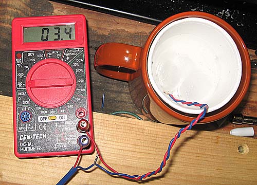
Cheap Digital Multimeter and Ice Water Reference.
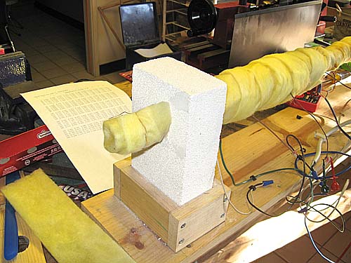
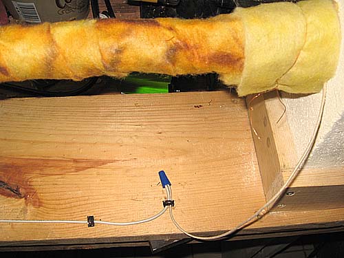
For control I put one thermocouple right in the middle of the length of the tube held in place with a hose clamp, and several more at 6" intervals out to the end for test purposes in getting the temperature equal. I later realized I didn't need the others because I could bore a small hole in an end cap and insert a thermocouple long enough to reach the middle and move it a measured amount to get the temparature at other locations. Before I started testing, I put one wrap of fiberglass information over the length of the tube between the two bricks.
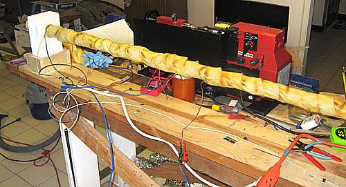
One Wrap of Fiberglass.
The stuff I used was about 3" wide by about 1/4" thick. Then I started to test. I ran the dimmer control up to full power until around 175° C or 350° F was reached and then backed off until I found a setting where that temperatue would hold. After it had come to equilibrium, I measured the other positions. Here are the results.
| Middle | 6" | 12" | 18" | 24" | 30" |
| 172° | 172° | 160° | 150° | 138° | 96° |
This was not too bad but I needed to do better. The results suggested more insulation on the ends. A second layer between 30" and 16" from the middle gave the following results
| Middle | 6" | 12" | 18" | 24" | 30" |
| 170° | 170° | 168° | 168° | 162° | 116° |
Considerable improvement, seemed to be on the right track. Added a third layer between 30" and 20" from the middle for these results.
| Middle | 6" | 12" | 18" | 24" | 30" |
| 172° | 174° | 174° | 175° | 174° | 128° |
This is looking about right. Applied the same wraps to the other end for these results.
| Middle | 6" | 12" | 18" | 24" | 30" |
| 170° | 174° | 179° | 181° | 181° | 140° |
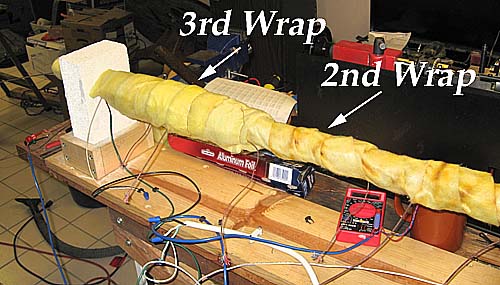
Second and Third Wraps Applied.
Rather than keep chasing this, I measured with the thermocouple on the inside to get this result
| Middle | 6" | 12" | 18" | 24" | 30" |
| 177° | 177° | 177° | 179° | 177° | 138° |
So for 24" on either side of the middle it looks like I have a reasonably uniform temperature. The heating cord only runs to the 30" point so there is 6" unheated on the ends which accounts for the drop there. It does help to add a little wrap of fiberglass on the end as shown here.
To improve on this, it seemed to need more heat near the ends, so the cord wraps were redistributed as shown below.
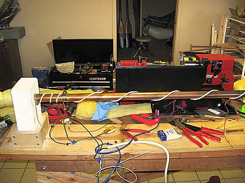
Redistributed Heating Cord--Same on Right End
With the insulation reinstalled as before the result of this was
| Middle | 6" | 12" | 18" | 24" | 27" | 30" |
| 172° | 172° | 170° | 172° | 180° | 185° | 172° |
The temperature drop at the end was moved further out and compressed over a smaller region, but more tweaking of the insulation was needed. As I did this the temperature at the middle would drift around even is extra insulation was nowhere near the middle, so at this point I decided to put a PID controller on with a thermocouple attached to the middle for a control point. This stabilized the temperature at the middle quite nicely and made the further adjustment of the insulation to equaliize the temperature much easier. My final result was
| Middle | 6" | 12" | 18" | 24" | 27" | 30" |
| 178° | 178° | 178° | 174° | 176° | 179° | 172° |
Wiring Details
The heating cord is a single conductor with a lead coming out each end. Wiring it, and connecting it to power is as shown in the next two pictures.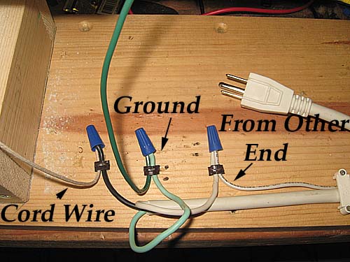
Wiring to 3 Condutor Power Cord
A cheap source of a good 3 conductor cord was a $3 strip outlet which I scrapped for it. The black wire is connected to one end of heating cord, the white wire to the other end, and the green wire, which is ground, is connected to the copper tube. Black, white and green are standard electrical code colors to the hot side, the neutral side, and ground respectively. Connections are made with wire nuts. The wires are held in place with insulated staples.
Connection at the Other End
The PID Controller
What a Proportiional-Integral-Differential controller does is to stabilize temperature to a set value by applying heat at just the right rate to bring it to the set value in the minimum amount of time while damping the oscillation about the set value. The following is a very explicit description of how I put in a specific PID controller.The PID Controller Parts
The PID controller I got was from Auber Intruments, their Universal 1/32 DIN PID Temperature Controller http://auberins.com/index.php?main_page=product_info&cPath=1&products_id=14 To go with it I got a 25 amp solid state relay http://auberins.com/index.php?main_page=product_info&cPath=2&products_id=9. I built it up in a 3x4x5" electronic project box which I go from a local electronics store. Other parts needed were from the local hardware store.They were
- A three conductor extension cord about 6' long.
- NM (non-metallic) connectors for holding the cord where it passes in and out of the box, 2 needed.
- Spade lugs for #16-#14 wire to fit #6 stud for connecting to the controller.
- Spade lugs for #16-#14 wire to fit #10 stud for connecting to the power terminals of the relay and to ground.
- 10-32 1/2" screws and nuts to hold the relay to the box--2 needed
- Black, white, and green stranded copper wire, #16 or #14, about 2' of each.
- Toggle switch single pole single throw (SPST) with screw terminals.
Assembly
Cut a rectangular hole in the box about 0.900" x 1.800" for the control unit. Put it where it won't crowd the relay which is screwed to the box. Bore holes for the relay mounting, the toggle switch and the NM connectors.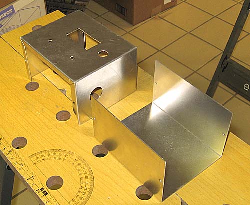
The box with all the holes cut
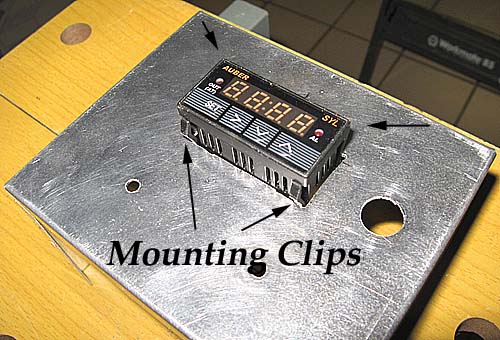
Mount all the parts as shown in the picture below. There are spring clips built into the control unit which hold it when it is slid into the hole.
Cut the extension cord about 14" from the socket end and strip about 4" of the outer cover off each of the cut ends and pass them through the NM connectors and clamp them with the screws.
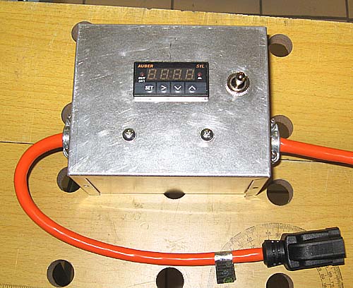
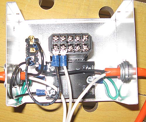
Assembled Box
Wiring the Contoller
To make connection to a spade lug, strip off about !/4" of insulation from a wire, insert it in the lug and crimp it with an electricians tool
Electrician's Tool
Starting the Wiring
- Crimp a #10 spade lug to the black wire of the output cord and connect to the T1 terminal on the relay. There is gray plastic cover on the relay you will have to take off to get at the terminals.
- Crimp a #10 spade lug to the green wire of the output cord and ground it by connecting to one of the mounting screws of the relay.
- Crimp a #10 spade lug to the green wire of the input cord and ground it by connecting to the other mounting screw of the relay.
- Crimp a #6 spade lug to the black wire of the input cord and connect it to a termiinal of the toggle switch.
- Take a 4" piece of black wire, crimp a #6 lug to one end and connect to the other teminal of the switch. To the other end of the wire, crimp a #10 lug and connect to L1 terminal of the relay.
- With another 4" piece of black wire, crimp #6 lugs to both ends and connect between the same terminal of the switch as the last one and the terminal 1 of the controller.
- Crimp a #6 lug to one end of a 4" piece of white wire and connect to the terminal 2 of he controller. Strip the other end and twist together with the white wires from the input and output cords and screw a wire nut on the twist.
- Crimp a #6 lug on one end of a 4" piece of green wire and connect to termal 3 of the controller. Crimp a #10 lug to the other end and ground it by connecting it to one of the mounting screws of the relay.
- Crimp #6 lugs to both ends of a 4" piece of black wire. Connect one end to terminal 9 of the controlller and the other to the A2(-) terminal of the relay..
- Crimp #6 lugs to both ends of a 4" piece of white wire. Connect one end to terminal 10 of the controller and the other to the A1(+) terminal of the relay.
- Make a thermocouple as described above. Connect the Chromel wire (yellow insulation) to terminal 7 of the controller and the Alumel wire (red insulation) to teminal 6.
- Clamp the junction end of the thermocouple to the copper tube of the oven about in the middle with a stainless steel hose clamp.
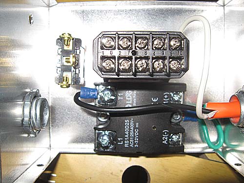
More Wiring
Setup and Operation
The controller comes with a manual which may be confusing. Hopefully this procedure list will help. To setup the controller plug it in, but don't plug in the oven. I strongly recommend running it from a GFI (Ground Fault Interrupt) protected outlet. Turn it on. On the front panel are four buttons, Set, >, ^, and v. The display has four columns.To Setup:
- Push the Set button
- Enter the code for setup, 0089. Do this by using the > button choose the column and the ^ and v buttons to set the numbers.
- Push the Set button. IntY should appear in the display. Push Set again. A t should appear in the display indicating that a copper constantan type T thermocouple is to be used, If t does not appear push the ^ button until it does. Push Set.
- Push ^, outY should appear. Push Set, if 2 does not appear, push ^ until it does. Push Set.
- Push ^, Hy should appear. Push Set, if 0003 does not appear, use the >, ^ and < span style="font-weight: bold;">v buttons to change it to 0003. Push Set.
- Push ^. Atdu should appear, Push Set. If 000 does not appear, use the >, ^ and v buttons to change it to 000. Push Set.
- Push ^. PSb should appear. Push Set. if 0000 does not appear, use the >, ^ and v buttons to change it to 0000. Push Set.
- Push ^. rd should appear. Push Set. if 0 does not appear, use ^ to change it. Push Set.
- Push ^. Corf should appear. Push Set. Use ^ to set it to 1 to display temperature in °F or 0 for °C. Push Set.
- End should appear. Setup is done.
To Set a Temperature:
- Push the Set button.
- Enter the code for temperature setting, 0001. Do this by using the > button choose the column and the ^ and v buttons to set the numbers.
- Push the Set button. Su should appear in the display. Push Set again. Use the >, ^ and v buttons to change it to the desired value. Push Set.
- Push ^. AH1 should appear. Push Set. Use the >, ^ and v buttons to set the high temperature where the alarm (AL) light goes on. Push Set.
- Push ^. AL1 should appear. Push Set. Use the >, ^ and v buttons to set the temperature where the alarm (AL) light goes off. Push Set.
- Push ^. End should appear. Push Set.
At this point it's done.
Using the Toaster
The way I heat treat my bamboo is to attach a thermcouple fed through a hole in the cap to the middle of the bundles of rough beveled strips . I set the oven to 275-300 F. It comes to this temperature as indicated by the PID controller in a few minutes. The bamboo temperature, as measured by the attached thermocouple, lags the oven temperature for up to an hour or so. Considerable amounts of steam come out the holes in the ends of the oven. It only takes one calorie per gram per degree C of absorbed water in the bamboo to raise its temperature to the boiling point, but then it takes 540 calories per gram to vaporize the water. While this is going on the temperature of the bamboo will be stuck pretty much at the boiling point of water, 212 F. When the bamboo does reach the oven temperature, I consider I am no longer vaporizing water. I raise the oven set point to 350 F, my heat treating temperature. The oven and the bamboo temperatures then reach 350 F in about 5 minutes. I hold it there for 30 minutes and then remove the bamboo from the oven. I do things this way now because I get a more uniform color of my heat treated bamboo, and a more clear cut knowledge of the time it spent at heat treating temperature.I use epon for gluing my bamboo and use the toaster to heat set it. I set the oven to 180 F and cook for 4 hours just as it says in the directions on the bottle.