An Implementation of a Baginski Beveler
by Mike McGuireUPDATED DESIGN I have replaced the anvil arm with a dovetail arrangement. See Below.
It turns out to be quite easy to remove a grinding wheel and its sheet metal shield and attach baseplate for the beveler using the mounting holes for the shield.
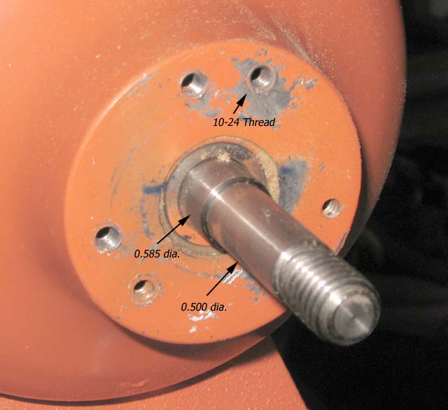
The mounting screws are 10-24 thread. The shaft is 0.500", stepping up to 0.585". If you do this on the left end of the grinder, don't lose the shaft nut--it's a left hand metric thread 12-1.5.
Making the wheel.
The most difficult part to make is the wheel. For that one needs a lathe, but not much of one. It was at the limit of the capabilities of the 7 X 10 Harbor Freight Mini-Lathe I have, but possible. The outside jaws of the chuck will hold a 3" diameter piece at maximum. This turns out to be about as large as you want to go with this grinder--it will lug down if one tries to feed a strip too fast. I have in mind making some two-hand rods which will require big strips so I decided I wanted a depth of the Vee-groove of 0.5". Now the outside jaws of the chuck are about 0.25" deep and the half width of a 0.5" groove is 0.288", so the starting point would be a couple of aluminum discs 3" diameter by 5/8" thick to clear the jaws while cutting the bevel. These I got from Online Metals for about $7 for the two. What they do when they make a specified cut is guarantee one will get at least the minimum and up to 1/8" more. The price was mostly the cost of cutting. The cuts were pretty smooth and did not require deep facing cuts to clean up.So what I did was first face both sides to about 0.600 thick, and bore a 0.500 hole through the center

Accurately measuring the depth of the bevel as it's being cut is a problem, so I registered a sharp pointed bit at the edge, moved it 0.500" in accurately with the cross feed and marked a circle of the diameter where the bevel would be done. On the second disk, I copped to the idea of painting the disk with a felt pen before making the mark to enhance contrast. Unfortunately the swarf from cutting the bevel pretty much scrubbed it off. Probably good layout dye would have worked better.
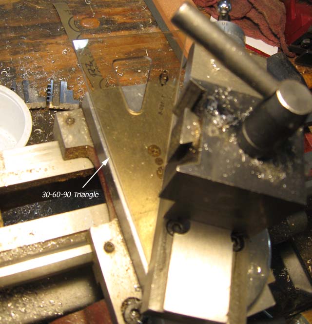
Cutting the bevel requires moving the cutting bit with the compound set to 30 degrees from the cross slide direction. There is an angle scale on the lathe but it doesn't go that far. However it's easy to do with a 30-60-90 drawing triangle.
The bevel is cut by moving the cross slide in a few thousands, and moving the compound through the range where it cuts. It was possible to cut going both in and out with the compound. When I got close to the limit line, I made the cuts just from inside.
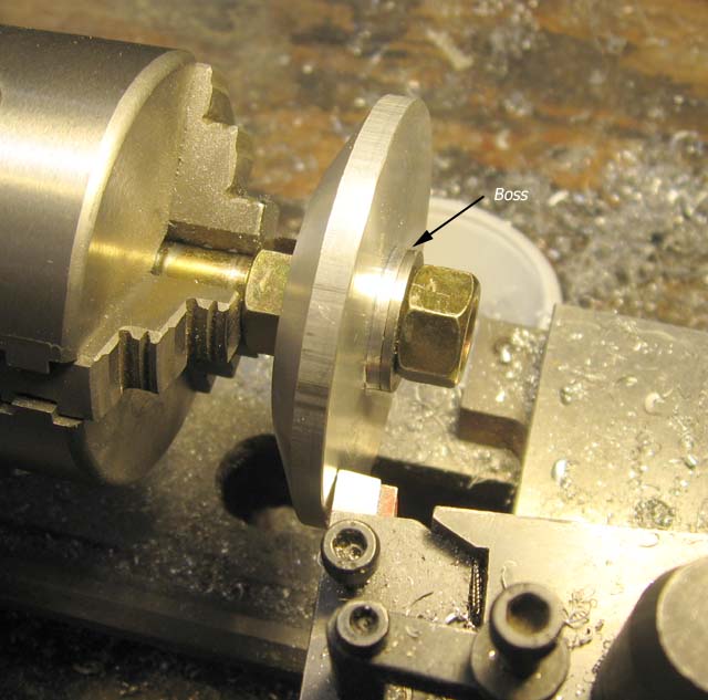
It's probably not necessary, but to lighten the wheel, it can be mounted on a 1/2" bolt and faced down to the diameter of the washer underneath the nut. To get good concentricity there, I bored a couple of 7/16" washers to 1/2". When the cut is done, there is a boss there at the original thickness.
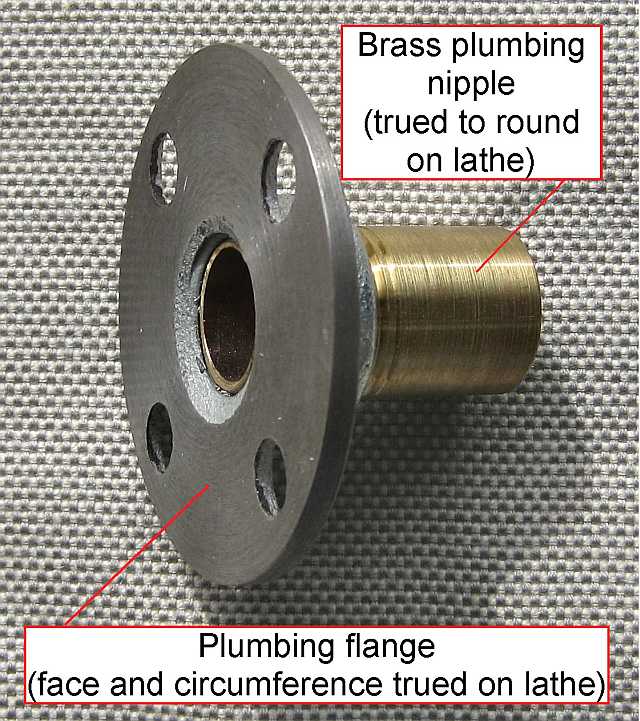
Tim Anderson had an alternate approach to holding the disks with a faceplate arrangement he made. This enabled him to cut 4 inch diameter disks on a similar lathe system to mine. However 3 inch diameter disks are about the maximum the grinder I used will handle without stalling. He uses a large router which can handle the 4 inch disks.
Gluing the Abrasive on.
The surface to glue the abrasive to is technically speaking the frustrum of a cone. There is a discussion of this geometry and the formulas needed for setting up a strip that will lay flat on the surface without wrinkles at this link. Reduced to the situation at hand one draws two concentric circles on the back of the sandpaper with a compass. For the 60 degree setup we have here the inner radius is 1.155 times the inner radius of wheel and the outer radius is 1.155 times the outer radius of it. A 48 degree pie slice out of it will have the ends just meeting without overlap. For a quad strip beveler, the factor would be 1.414 with a 105 degree slice, and for a penta strip beveler the factor would be 1.236 with a 69 degree slice.I have used epoxy, Barge cement (contact cement) and adhesive backed sandpaper and the all worked fine. Heating the disks with a head gun works for getting off worn out paper.
Adhesive backed sandpaper here.
Setting Up the Beveler
The beveler is set up on a 5" x 10" x 3/8" red oak baseplate. The sheet metal shield can be used as a template for locating the mounting holes.
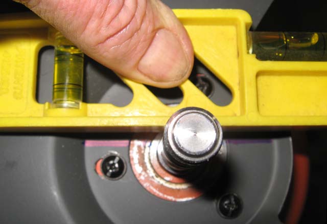
The tricky part is getting it level. After making sure the grinder was sitting level, I used a level to draw a line on the shield which I transfered along with the mounting holes to the baseplate. I got it close but not quite right.
The in feed and out feed shelves shout be in line with the groove in the wheel and level--it's not level in the picture. Use a triangular strip laid in there to locate these.
UPDATED DESIGN I have replaced the anvil arm with a dovetail arrangement. See Below.
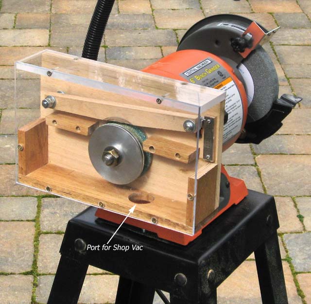
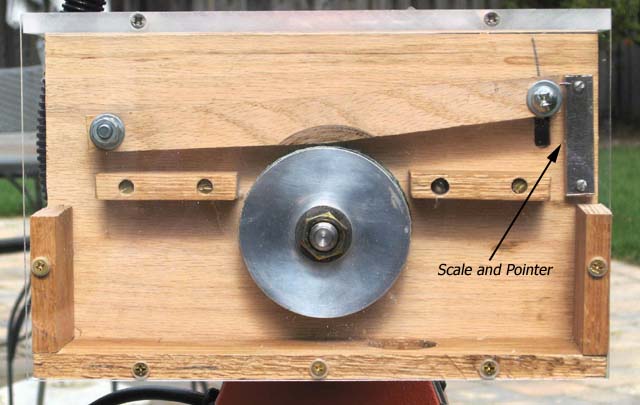
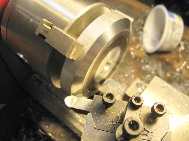
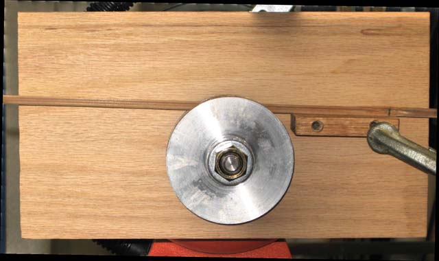
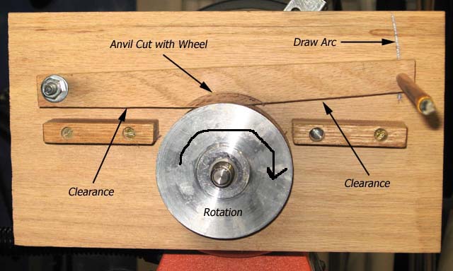
The anvil bar should be set so the top is level when cutting about the smallest dimension strip wanted. It pivots on a 1/4-20 bolt, and is spaced out with nuts and washers to be centered on the wheel. Use the wheel itself to cut the contact area at the wheel, but leave some flat edge, don't cut it sharp. The other end is to be clamped with a 1/4-20 bolt the moves in a slot, also with nuts and washers for spacing. I turned a pencil down to fit in a 1/4" hole and scribed the arc of the slot and then drilled an filed the slot out. There are clearances cut on the input and output side of the anvil. The picture at the top of this article shows a piece of metal scale and a pointer for reproducing a strip size. The rest of it is a matter of building an enclosure so that a shop vac can effectively collect the dust.
Using the beveler
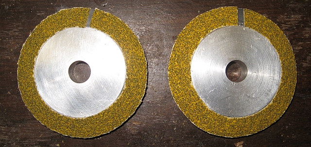
The strips need to have their nodes well flattened and be reasonably straight. While soaking the strips makes flattening nodes easier, dry them out before beveling. Wet strips will rapidly clog the wheels. Wear gloves while handling the strips--the edges get sharp. Keep a good hold on a strip. If you don't it will launch a strip back out clear across the room. While you can do a strip in one pass it seem better to take two or three to get to desired dimension. If you jam a strip in too fast, it can stall the grinder. If this happens, back off a bit while it comes back to speed, and feed in more slowly. When cutting extra wide strips, say for the butt section of a spey rod, the spacing between the wheels will need to be widened with a washer or two so the strip fits between the wheels for the first cut or two.After some number of strips have been beveled, the abrasive will become clogged with resin from the bamboo and not cut as efficiently. The fix is to clean it rather than replace it. There are resin and gum removers available form woodworking retailers. I got some very effective stuff from Woodcraft.
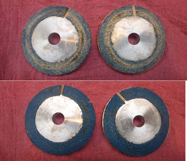
Wheels before and after cleaning.
Link to Tim Anderson's beveler article
UPDATED DESIGN Dovetail Anvil
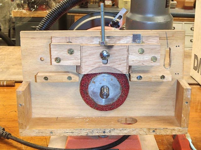
On of the cutter wheels is removed to show the cut on the anvil. The carriage bolt through the anvil clamps it in place. The screw thread sticking up is for seeting the dimension.
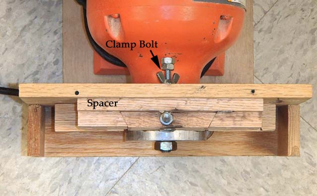
Top view: the thickness of the spacer is adjusted to center the anvil over the wheel.
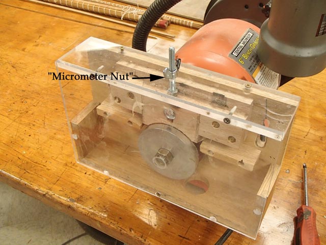
This is what it looks like all assembled with dust cover. The "micrometer nut:" is a nylon insert wing nut so it stays put wherever set. It's a 1/4-20 thread, so one 360 rotation moves the anvil 0.050 inches. Zero it by putting it in contact with the wheel while micrometer nut is in contact with the case. Tturn it to desired dimension and set clamp bolt again making sure the micrometer nut is flush with the case. It's not high precision--check with cut on a piece of scrap material.